All lines
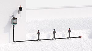
Above-ground

Drip irrigation

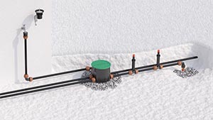
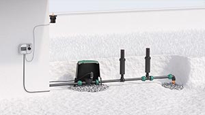
Underground

Online catalogue
The RF module is fully watertight and will function even when installed permanently under water at a depth of up to one metre (ingress protection IP68).
It can be installed in the open, or in a cup underground.
To ensure it is watertight, make sure that the control unit is aligned and inserted in the guides (3), and that the clear cover is fully screwed on right up to the seal, which must be correctly positioned.
The RF module can operate up to four 9V bistable solenoid valves. Connect the black wire to the negative pole (black wire) of each solenoid valve (common). Connect the red wire to the positive pole (red wire) of each solenoid valve.
Unscrew the transparent cover. Remove the control unit. Unscrew the battery compartment plug, take out the battery-holder, and if present, remove the drained batteries.
Fit the new batteries in the holder, observing the correct polarity. Retighten the cap, checking that the seal is positioned correctly in its seat. Align the control unit with the guide on the casing and fit it back into place. Retighten the transparent cover, checking that the seal is in its seat.
Warning: use branded AAA Alkaline 1.5 V batteries (not rechargeable) only.
Once the batteries are fitted, an initialization routine will start (display Leds light up in sequence, valves close in sequence).
Remove the cover on the back of the remote control and insert 2 branded alkaline AAA 1.5V batteries (not rechargeable).
N.B. Match up the poles as marked inside the compartment (++ - -).
30 seconds after having fitted the batteries, or pressed any of the buttons, the Leds on the panel will go out: to refresh the display, press any button.
The RF module can be programmed automatically using the RF remote control (code 8347 manages up to 2 RF devices/ code 8348 manages up to 6 RF devices), sold separately. Without the RF remote control, you can only irrigate manually.
Symbols 1, 2, 3, 4
Status: Green light on
Situation: Indicates that the corresponding solenoid valve is open.
Status: Flashing green light
Situation: Indicates the solenoid valve currently selected.
Symbol OK
Status: Flashing green light
Situation: Indicates that the selected solenoid valve is open in manual mode. Pressing the OK button will close the valve.
Indicates the status of the RF Rain Sensor (only if the RF Remote Control is set up with the RAIN SENSOR function activated for the RF unit).
Status: Permanently alight
Situation: Watering programme suspended by activation of the RF Rain Sensor.
Status: Blinking
Situation: The RF solenoid valve has received no signal from the RF Rain Sensor for more than 24 hours for one of the following reasons:
1) the batteries of the RF Rain Sensor are flat (replace the batteries);
2) the radio frequency signal is too weak (position the sensor nearer to the RF unit).
Symbol RF
Indicates that the unit is dialoguing with the RF Remote Control.
Status: Red, blinking
Situation: Awaiting connection with the RF Remote Control.
Status: Red, permanently alight
Situation: RF Remote Control-unit connection procedure in progress.
Status: Green, blinking
Situation: Data transmission in progress.
Symbol LOW BATT
Indicates the charge status of the batteries.
CLOCK Symbol
Indicates the operational status of the remote control.
Status: Red, permanently alight
Situation: Not paired with remote control. No automatic watering entered or transferred.
Solutions: Connection required.
Status: Alternating Red/Green
Situation: Connected. Irrigation programmes NOT yet transferred. Automatic watering suspended.
Solutions: Transfer the watering programmes from the remote control to the unit.
Status: Green, permanently alight
Situation: Connected, time synchronized. Watering programmes set to run automatically. Automatic watering enabled.
Status: Green blinking
Situation: Paired, time NOT synchronised between the two devices (for example, because the time has been lost due to a prolonged period without batteries). the irrigation programmes will be run at different times to those set on the RF remote control.
Solutions: Reprogramme the module.
The red colour of the clock symbol, whether permanently alight or blinking, warns that the RF unit is not programmed for automatic watering.
Solenoid valves can be opened and closed manually using either the RF unit or the remote control (see the relevant section).
Use the arrows to select a solenoid valve.
Press the OK button to open the selected solenoid valve (when the valve is open, the OK symbol starts to blink and the corresponding number lights up, remaining permanently on).
Press OK to shut off the open solenoid valve manually or wait 5 minutes for it to close automatically.
Manually opening a solenoid valve interrupts any automatic irrigation in progress.
1) Indicate the programmed start times (start time) for automatic watering
2) Indicates battery level
3) Indicates the line which is being programmed
4) Indicate which programmes (only A, only B, both A and B neither A nor B) are enabled
5) Indicates the page for testing and manual watering
6) Indicates that we are in change parameter mode
7) Shows start time pages
8) Indicate the time or, in the programming pages, the run time and start time of watering
9) Indicates that watering is in progress
10) Indicates the day of the week; in programming, it indicates the day of the week in which watering is required and with which of the two programmes
Only three keys let you set all the parameters.
The arrows let you scroll through the various pages in order to select the one desired.
The OK key lets you access the EDITING of the parameter displayed. When is pressed, OK appears in the bottom left display.
With OK, the arrows turn on and let you edit the value of the parameter displayed.
Once you have reached the desired value, press OK to confirm the change. At the bottom right of the display, “OK” will show.
It is now possible to go back to the page with the arrows.
If a key is not pressed for approximately 5 minutes, the water timer automatically returns to the date and hour page, without confirming the changes in progress.
To pair the devices, keep them no less than 50 cm and no more than 10 metres apart and ensure there are no obstacles. Press any button to activate the unit.
Press the three RF module buttons at the same time and hold for at least 5 seconds, until the red LEDs with the CLOCK and RF symbols start to flash.
Hold down the Remote control RF UNIT button to select the RF Unit number to which the RF module is to be associated.
Insert a pointy object into hole S1 in the RF remote control for a few seconds: a radio frequency icon will appear.
The Remote control RF display flashes indicating that the two components are trying to establish a radio frequency connection.
The outcome of the connection procedure is indicated on the RF Remote Control display when the RF symbol stops blinking.
(A) Connection failed: RF symbol permanently alight and error symbol blinking. Repeat the connection procedure.
(B) Connection successful: RF symbol off. The paired unit will show (e.g. 1 AB Unit).
Regardless of the outcome of the pairing, all the symbols will light up in sequence on the RF module display.
If pairing is successful, RF module will display the clock symbol alternating red/green.
The display provides information about all the programming pages in the order they appear: the arrows allow the user to scroll through the different pages. The OK key lets you access the EDITING of the parameter displayed.
Warning: a start time cannot be set for each individual line. Only the first start time is set. The other lines will come on one by one depending on the times selected for each of them. To set the other three start times, you need to add together the minutes entered for each line, plus one minute automatically calculated by the timer. Watering cycles continue in sequence (once line 1 is finished, line 2 starts and so forth).
The unit can control up to 4 irrigation lines. On the remote control, each line has two independent programmes, A and B. In both programmes up to 4 daily start times can be set in a 24-hour span. Each start time begins a watering cycle on all 4 lines, making each of them work one after the other for the run time set, which can be from a minimum of 1 minute up to a maximum of 60 minutes.
Warning: a start time cannot be set for each individual line. Only the first start time is set. The other lines will come on one by one depending on the times selected for each of them. To set the other three start times, you need to add together the minutes entered for each line, plus one minute automatically calculated by the timer. Watering cycles continue in sequence (once line 1 is finished, line 2 starts and so forth).
Press OK and use the two arrows to set the desired time. Press OK to confirm.
Use the arrows to set the day of the week and press OK.
The days are shown as: S Sunday, M Monday, T Tuesday, W Wednesday, T Thursday, F Friday, S Saturday.
The RUN TIME page allows the user to set a watering run time for programme A and programme B for each LINE. The watering cycle run time for each line can be set from 1 to 60 minutes.
From the page showing the time, press UNIT until you arrive at the unit to be programmed.
From the RUN TIME page, press OK to enable modification, the symbol OK flashes indicating that the parameters displayed can be modified and require a setting confirmation. Using the arrows changes the value displayed (by pressing and holding the keys, the value will change more quickly). Press OK to confirm the set value.
By pressing the right arrow the user moves to the RUN TIME setting of the next line up to a maximum of 4 lines to form a WATERING CYCLE.
If a watering cycle does not include the use of a specific line, simply set the watering run time of that line to OFF.
The START TIME page allows the user to set up to start times per day for the WATERING CYCLE for programme A and 4 times for programme B.
From the START TIME page, press OK to enable modification of the START TIME 1, the symbol OK flashes indicating that the parameters displayed can be modified and require a setting confirmation. Using the arrows change the value displayed.
Press OK to confirm the set value.
If necessary, set the times of the next START TIMES 2, 3, 4 by pressing the right arrow and repeating the operations described above.
Warning: the timer automatically resets the 4 daily START TIMES for each programme A or B to prevent a watering cycle from starting before the previous one has been completed or from going beyond the 24 hours in the day. It is possible to overlap the times of the programme A and programme B watering cycles (if the system does not have a sufficient flow rate, this could have a negative impact on the quality of the watering).
With the weekly programming (WEEKLY SCHEDULE) the user selects the days of the week on which the set Watering cycles are activated.
From the WEEKLY SCHEDULE page, press OK, the symbol S flashes (Sunday).
Use the arrows to move to the desired day and press OK to select which programmes to start on that day (only A, only B, both A and B, neither A nor B). Press the OK button several times to enable or disable the daily programmes.
The days are shown as: S Sunday, M Monday, T Tuesday, W Wednesday, T Thursday, F Friday, S Saturday.
To exit use the arrows to move to EXIT; when it flashes, press OK.
The settings will be saved.
The RF unit recognises the signal of an installed RF Rain Sensor, provided the devices are no more than 30 m away (obstacle free) and there are no other radio frequency signals.
From the RAIN SENSOR page press OK, activates when the Rain Sensor RF activates/deactivates.
Press the right arrow to move the status from “NO” (sensor deactivated) to “YES” (sensor activated) and vice versa.
Confirm by pressing OK.
Recognition between the devices takes about 5-10 minutes.
Status of Rain Sensor RF:
symbol ON: Sensor EMPTY or not active for the water timer.
Symbol permanently on: Sensor FULL or active for the water timer. With the sensor FULL any watering programmes are interrupted and other programmes start automatically while the symbol remains active.
Symbol active and flashing: the water timer has not received any information from the Rain Sensor RF for more than 24 hours and is working independently from the sensor. Check the Rain Sensor RF installation and batteries.
Warning: the RF module can only be combined with the RF Rain Sensor (code 90831), not the wired Rain Sensor (code 90915).
From the TEST page press OK. Use the arrows to select the solenoid valve to be activated (the number 1, 2, 3, 4 indicates which solenoid valve is selected).
Press OK to open the selected solenoid valve (when the valve is open the OK symbol flashes).
Manual irrigation is factory preset to run for 5 minutes, and is modifiable between minimum 1 minute and maximum 60 minutes.
If you want to stop it sooner, press OK. OFF appears on the display.
Move to the page where TEST is displayed with the symbols OK and EXIT flashing. Press OK to exit TEST/manual mode.
The DAY/TIME screen is normally shown on the display; press the UNIT button, use the arrows to select the unit and press OK.
Press the arrows to enable programme A, programme B or both programmes, or to set them to OFF.
N.B. Programme A irrigation cycles can overlap with programme B irrigation cycles (if there is an insufficient flow rate in the system, this may affect the irrigation quality).
Once the selection has been made, press OK to confirm enabling of the programmes displayed.
Keep the devices no less than 50 cm and no more than 10 metres apart and ensure there are no obstacles.
Press the UNIT button to choose the unit and press the RF button. The flashing RF icon will be displayed on the remote control screen for a few seconds.
The subsequent disappearance of the RF symbol indicates that the update was successful. If ERR blinking appears on the remote control, bring the two devices closer together and repeat this operation. press the UNIT button several times to return to the DATE/TIME page.
Each change made from the RF remote control must be transferred to the RF module. After replacing the RF module batteries, synchronise the time from the RF remote control in the same way.
RESET restores factory settings, deleting all watering programmes and pairings with the RF Rain Sensor and the RF remote control.
To RESET, press both arrows at the same time and hold for 10 seconds, until all the symbols light up in sequence.
To reset the RF remote control, insert a pointy object in hole S1 and press both arrows at the same time and hold for 10 seconds.
At the end of the season, before the winter frosts, turn off the water and drain the system, manually opening the valves to run off the water remaining inside.
Remove the control unit and store it in a dry place, where the temperature does not fall below 3°C. Remember to remove the batteries.
At the start of the season, insert new batteries and close the lid, taking care to insert the seal correctly.
Connect the wires to the blue solenoid valve matching up the poles (red + black -) and reinsert the control unit, lining it up in the guides and taking care not to crush the wires. Always put the clear cover back on and fully close, checking that the seal is correctly in place.